
News
What Is OPGW in Transmission Lines and Why Is It Used?
Overhead transmission networks need both electrical protection and dependable communication. Optical Ground Wire, commonly called OPGW, combines these functions in one overhead cable. It replaces, or works alongside, a conventional shield wire above energized conductors.
Opgw In Transmission Line systems usually contain optical fibers inside a protected central tube. Aluminum strands carry fault current and help shield the line from lightning. Steel or aluminum-clad steel elements provide mechanical strength. This structure allows utilities to transmit voice, control, protection, and high-speed data between substations. The distinction matters. One cable performs two critical roles.
From a field perspective, OPGW performance depends on more than fiber count. Engineers must check span length, expected sag, short-circuit current, wind loading, ice conditions, and tower hardware. During installation, excessive pulling tension or a sharp bending radius can damage fibers without visible external marks. It must be tested. OTDR measurements, splice-loss records, and grounding checks help confirm system reliability before energization. At substations, carefully sealed termination boxes protect fibers from moisture and mechanical stress.
OPGW is not a universal answer for every transmission project. Existing towers may need structural verification, and replacement work can require carefully planned outages. A technically suitable cable can still fail if fittings, bonding, or maintenance procedures are poorly selected. Utility specifications and applicable IEC standards should guide the design. This article explains how OPGW works, where it provides practical value, and which limitations engineers should consider before choosing it. Some project assumptions deserve another review. That caution improves long-term grid reliability.
What Is OPGW and Where Is It Installed?
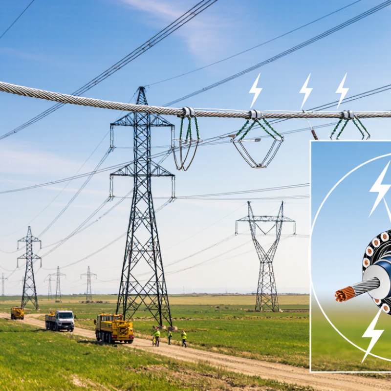
OPGW, or Optical Ground Wire, is installed at the highest position of an overhead transmission line. It replaces the traditional shield wire above phase conductors. Its metal strands protect the circuit from lightning and carry fault current toward tower grounding systems. Inside the same cable, optical fibers transmit voice, protection, and real-time grid data. This dual role saves tower space and avoids separate communication cables.
Where is OPGW installed? Utilities place it between transmission towers, usually along high-voltage routes, substations, and renewable-energy corridors. The International Energy Agency reported in Electricity Grids and Secure Energy Transitions that the world may need 80 million kilometers of new or refurbished grids by 2040. That expansion increases the value of reliable, fiber-based monitoring. IEC 60794-4-10 also provides requirements for optical ground wire cable performance. Field engineers still check span length, sag, wind loading, and short-circuit conditions before selecting a design. One detail is often underestimated: installation tension can damage fibers without visible external marks.
Tips: Confirm tower earthing before cable replacement. Measure optical loss after installation. Follow IEEE 524 guidance for stringing overhead conductors and cables. Keep spare fiber capacity when future substations are likely. A perfect design is rare. Local ice, heat, corrosion, and maintenance habits can change the result.

What Is OPGW in Transmission Lines and Why Is It Used?
Optical Ground Wire (OPGW) is a composite overhead cable that combines a lightning-shielding ground wire with optical fibers for high-speed communication. It is normally installed at the highest point of transmission towers, above the phase conductors, where it can protect the line from lightning and support protection, control, and telecommunications systems.
Reference Fiber Attenuation at Common Communication Wavelengths
The chart shows maximum attenuation values commonly specified for ITU-T G.652 single-mode optical fiber. Lower attenuation allows signals to travel farther before amplification or regeneration. Actual OPGW performance depends on the cable design, installation conditions, and fiber specification.
How OPGW Combines Grounding and Fiber-Optic Communication
OPGW is overhead ground wire with fiber-optic units inside. It sits at the top of a transmission tower. It performs two jobs at once. The metallic outer layers provide a path for lightning current and fault energy. The protected optical fibers carry voice, protection, and monitoring data. This arrangement saves tower space and supports faster grid communication. During installation, crews must control pulling tension and bending radius carefully. A small mistake can damage fibers without visible marks.
Inside the cable, fibers remain isolated from electrical current. Optical signals are not affected by electromagnetic interference from high-voltage conductors. Utilities can use this link for relay coordination, substation communication, and real-time equipment status. The cable also needs correct grounding at tower ends and suitable bonding along the line. Design teams should check span length, ice loading, sag, and short-circuit temperature. OPGW is strong, but it is not indestructible. Maintenance plans should include optical loss testing after installation and following severe storms.
Tips: Match the cable’s fiber count and thermal rating to the network plan. Inspect fittings, joints, and tower connections during routine patrols. Keep accurate test records. They reveal gradual deterioration. A practical warning: replacing a damaged section can be harder than expected, especially across steep terrain. Good design reduces that risk, but field conditions still deserve careful review.
What Is OPGW in Transmission Lines and Why Is It Used? - How OPGW Combines Grounding and Fiber-Optic Communication
| Data Dimension | Typical OPGW Information | Why It Matters in Transmission Lines |
|---|---|---|
| Primary Function | Combines an overhead ground wire with optical-fiber communication capability. | Provides lightning shielding and a protected communications path on the same transmission-line structure. |
| Full Name | Optical Ground Wire. | Describes the cable’s dual role as both a grounding conductor and a fiber-optic cable. |
| Typical Installation Position | Installed at the top of transmission towers, above the phase conductors. | The elevated position helps intercept lightning and maintain a shielding angle over energized conductors. |
| Optical Fiber Count | Common designs contain approximately 12 to 48 fibers; higher-count designs are also available. | Fiber capacity can support protection signaling, supervisory control, voice, data, and utility telecommunications. |
| Fiber Type | Usually single-mode fiber compliant with applicable telecommunications standards. | Single-mode fiber supports long-distance, high-bandwidth transmission with low attenuation. |
| Typical Outside Diameter | Approximately 8 to 20 mm, depending on the electrical and mechanical design. | Diameter affects weight, wind loading, ice loading, fittings, and compatibility with existing towers. |
| Typical Cable Mass | Approximately 300 to 1,500 kg/km, depending on diameter, materials, and strength requirements. | The mass must be included in tower loading calculations and sag-tension analysis. |
| Rated Tensile Strength | Common designs range from roughly 40 to 150 kN, with project-specific values outside this range. | Strength must withstand installation loads, wind, ice, vibration, and long-term mechanical stress. |
| Short-Circuit Current Capability | Often designed for approximately 10 to 40 kA for 0.5 to 1 second, subject to the selected conductor design. | The cable must safely carry fault current until protective devices clear the fault. |
| Electrical Resistance | Common designs are approximately 0.2 to 1.0 ohm/km at 20°C. | Lower resistance helps reduce voltage rise and heating during fault-current events. |
| Optical Attenuation | For many single-mode fibers, approximately 0.22 to 0.35 dB/km at common operating wavelengths. | Lower attenuation increases communication distance and available optical power margin. |
| Operating Temperature | Typically rated for approximately -40°C to +70°C, with some designs supporting higher conductor temperatures. | Temperature limits influence sag, optical performance, material selection, and emergency operating conditions. |
| Lightning and Fault Protection | The metallic layers provide a conductive path for lightning current and phase-to-ground fault current. | Helps protect phase conductors, towers, insulation, and connected equipment when properly grounded. |
| Communication Applications | Teleprotection, SCADA, substation communications, operational voice, monitoring, and network data. | Enables fast, reliable information exchange for grid control, fault detection, and system coordination. |
| Main Advantages | Dual functionality, electromagnetic immunity of optical fibers, high bandwidth, and efficient use of tower space. | Reduces the need for separate grounding and communication infrastructure along the line route. |
| Key Design Considerations | Tower geometry, span length, wind and ice conditions, fault current, sag, vibration, fiber capacity, and installation method. | Correct design ensures mechanical reliability, electrical safety, optical performance, and compatibility with the transmission corridor. |
| Common Reference Standards | IEC 60794-4, IEEE 1138, IEC 61089, and applicable national utility specifications. | Standards define or guide requirements for optical performance, mechanical behavior, electrical properties, testing, and installation. |
Note: The values shown are representative engineering ranges. Final OPGW specifications should be selected according to the transmission-line design, environmental conditions, fault-current requirements, and applicable standards.
What Are the Main Components of an OPGW Cable?
What Is OPGW in Transmission Lines and Why Is It Used?
An OPGW cable combines overhead grounding and fiber-optic communication in one transmission-line component. It usually replaces the conventional shield wire above the phase conductors. The cable helps discharge lightning currents while carrying high-speed signals for protection, monitoring, and operational communication.
The Optical Unit
The optical unit is the communication core. It contains several glass fibers, often placed inside a sealed stainless-steel tube or protected fiber unit. The tube may contain gel or dry water-blocking material. This protection limits moisture movement after sheath damage. Some designs include a central strength member to control tension and bending. Small details matter here.
Metallic Structure
Around the optical unit, metallic wires form the mechanical and electrical structure. Aluminum alloy wires can reduce weight and improve conductivity. Aluminum-clad steel or galvanized steel wires provide higher tensile strength and support short-circuit current performance.
The exact combination depends on span length, wind loading, fault current, and tower design. A cable that looks suitable on paper may still fail a field installation review.
Field Inspection and Installation
During field inspections, technicians check strand damage, uneven tension, corrosion, and poor bonding at fittings. The end closures and suspension hardware are not part of the cable body, but they strongly affect reliability. Engineers should also verify fiber attenuation, bend limits, thermal ratings, and sag calculations before installation. Water blocking is useful, but it should not be treated as permanent protection against every installation mistake.
How Is OPGW Installed on Transmission Lines?
Installing OPGW on transmission lines requires careful planning, controlled tension, and experienced line crews. Engineers survey tower positions, conductor clearances, access roads, and existing grounding points before work begins. They also check weather conditions, because strong wind can make the fiber cable swing against tower steel.
The crew places the OPGW reel on a stable stand near the line route. A pilot rope pulls the cable through each tower, while a tensioner controls its movement. The cable should never drag across the ground or scrape against sharp metal. Crews use approved stringing blocks, communication radios, and calibrated tension equipment during this stage. Small mistakes matter. Excessive tension may damage the cable or affect its final sag.
After stringing, technicians adjust sag according to the approved line design. They secure the cable with suspension and tension hardware, then bond it to the tower grounding system. Splicing enclosures are installed carefully, usually where maintenance access is practical and vibration is limited. Technicians test optical continuity, attenuation, grounding resistance, and mechanical security before energizing the line. A neat installation is not always a perfect one. Experienced teams still recheck measurements, because temperature and tower movement can change the final result. Records should include test readings, splice locations, hardware checks, and any field adjustments.
What Benefits and Limitations Does OPGW Provide?
OPGW, or optical ground wire, combines a transmission line’s shield wire with optical fibers. It is installed near the top of towers, where it helps intercept lightning before faults reach energized conductors. Inside the metal strands, fibers carry signals for protection, monitoring, voice, and operational data. This dual function saves tower space and avoids building a separate communication route.
The main benefit is dependable, low-latency communication along the transmission corridor. Protection relays can exchange signals quickly during faults, helping isolate damaged sections. Operators can also receive data from substations, weather devices, and condition-monitoring equipment. OPGW usually provides strong mechanical support, while its metallic layer handles expected fault current. In remote areas, this combination can reduce maintenance on separate telecom infrastructure.
The limitations deserve equal attention. Installation may require outages, specialized tensioning equipment, and careful fiber splicing. A damaged cable can interrupt both grounding performance and communications. Ice, wind, tower movement, and high fault currents also affect service life. Fiber capacity is valuable, but it cannot fix poor network planning. The trade-off is easy to underestimate. A design may look efficient on paper, yet repair access can be difficult across mountains, forests, or private land. Engineers should check span loads, lightning exposure, fault-current duration, fiber redundancy, and future data demand before selecting OPGW. Cost estimates should include testing, emergency repair, and compatible terminal equipment, not only the cable itself.