
News
Why Use a Digital Signal Isolator?
Why does a digital signal need isolation when it carries only zeros and ones? In real equipment, those bits travel through copper, connectors, and noisy environments. A Digital Signal Isolator transfers logic information across an electrical barrier without a direct conductive path. That separation can help limit ground-loop currents, reduce noise coupling, and protect low-voltage control circuitry from disturbances on another side. Small detail. It matters.
Consider a motor controller sharing a cabinet with a sensor interface. Switching currents can shift the local ground potential, while long cables may collect interference. An isolator helps keep that disturbance from travelling straight into the processor’s input. It can also support communication between circuits with different ground references. The benefit depends on the system, though. An isolator is not a cure-all.
Choosing one requires more than checking the channel count. Engineers should compare data rate, propagation delay, isolation rating, common-mode transient immunity, power needs, and package layout. The surrounding board matters too: creepage, clearance, and routing affect the barrier’s real performance. Datasheets provide essential limits, but testing in the actual operating environment still matters. A noisy prototype may reveal issues a clean bench setup misses. That is worth remembering. This guide explains what digital signal isolators do, where they help, and what trade-offs deserve attention before selection. It also distinguishes signal isolation from broader system safety, which requires a complete design review.
What Is a Digital Signal Isolator?
Why Use a Digital Signal Isolator?
What Is a Digital Signal Isolator?
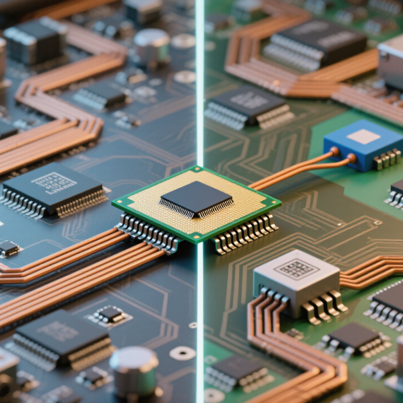
A digital signal isolator transfers logic-level data between circuits without a direct electrical connection. Inside, capacitive or magnetic coupling carries changing pulses across an insulating barrier. The barrier helps limit hazardous voltage and ground-loop noise from reaching sensitive electronics. Think of a motor drive sending a control pulse to a low-voltage controller: the information crosses, but the grounds remain separated. It is not a voltage converter, and it cannot replace correct circuit protection.
Designers assess working voltage, insulation rating, creepage, clearance, and common-mode transient immunity. IEC 60747-17:2020 specifies evaluation requirements for magnetic and capacitive couplers. Installation conditions matter, too. IEC 60664-1 gives a 1.14 altitude correction factor for clearance at 3,000 metres. That figure concerns insulation coordination; it is not a universal isolator rating. In practice, I would check the device’s test conditions against the actual board layout. A datasheet number alone can feel reassuring, perhaps too reassuring.
Tips: Match the isolator to the required data rate and isolation rating. Check transient immunity and package spacing. Then inspect the board’s creepage path. Small layout details matter.

How Does Digital Signal Isolation Work?
A digital signal isolator transfers logic information across a barrier without a direct conductive connection. At the input, a transmitter converts a changing logic state into a brief electric or magnetic signal. That signal crosses a tiny gap, then a receiver rebuilds the original high or low state. Think of a pulse crossing a glass wall: information gets through, but ordinary current does not.
Capacitive isolators couple pulses through an insulating dielectric; magnetic designs use a changing magnetic field across the barrier. IEC 60747-17:2020 specifies requirements for magnetic and capacitive couplers, including insulation-related testing. The barrier’s rating matters, but so do circuit-board spacing, package construction, and the voltage difference between grounds. No copper bridge. The signal still needs a clean path on each side.
Isolation does not automatically remove every glitch. Fast voltage changes can couple across the barrier, so engineers check common-mode transient immunity and layout. IEC 61000-4-2 defines ESD test levels including 2, 4, 6, and 8 kV contact discharge, and air discharge up to 15 kV. These are system-immunity test levels, not a guarantee that any isolator passes them. A practical check is to compare the isolator’s datasheet tests with the actual board environment; that detail is easy to overlook.
What Problems Can a Digital Signal Isolator Prevent?
A digital signal isolator transfers logic signals across an electrical barrier without a direct conductive connection. This separation can help prevent ground-loop currents when a sensor and controller sit at different ground potentials. It can also reduce the chance that voltage transients or electrical noise disrupt a data line. For example, a long cable near a motor may pick up interference, causing false readings or resets. Not every fault disappears. An isolator does not replace correct grounding, surge protection, or suitable wiring.
Without isolation, a fault on one side may travel through shared signal grounds into sensitive control electronics. Isolation limits that conductive path, helping protect interfaces and maintain communication in measurement and control systems. Choose a device by checking its working voltage, isolation rating, data rate, and common-mode transient immunity. A mismatch may cause timing errors or fail during real transients, so review the specifications carefully. Testing with actual cable lengths and switching loads can reveal problems that a quiet bench setup misses. Board layout matters, too; poor spacing can weaken an otherwise capable isolator.
Where Are Digital Signal Isolators Commonly Used?
Digital signal isolators are commonly used wherever low-voltage control signals meet hazardous or electrically noisy circuits. In factory automation, they separate PLC inputs, motor drives, and sensor networks from high-voltage equipment. A fast switching motor can put sharp interference on a cable; isolation helps protect the controller and preserve signal integrity. Noise matters. Engineers still need to check working voltage, transient ratings, creepage, and clearance for the actual installation.
Energy systems are another major setting. Solar inverters, battery management systems, and charging equipment use isolation between control electronics and power stages. The IEA’s Renewables 2023 report recorded nearly 510 GW of renewable capacity additions in 2023, almost 50% more than in 2022. More converters mean more points where reliable signal isolation matters. The IEA’s Global EV Outlook 2024 also reported nearly 14 million electric car sales in 2023, around 18% of all car sales. That growth brings isolators into vehicle battery monitoring and charging interfaces.
Isolators also appear in medical equipment and industrial communications, where a signal may cross between circuits with different ground potentials. In practice, the right device depends on data rate, isolation voltage, common-mode transient immunity, and power use. A design can look safe on paper and still fail under real switching noise. That detail is easy to miss. Industry reports describe market growth, not the suitability of any single component; application testing remains essential.
Why Use a Digital Signal Isolator?
Digital signal isolators transfer logic signals across a galvanic isolation barrier, helping protect circuits from hazardous voltage differences, ground loops, and electrical noise.
Common applications: industrial control and sensor interfaces, motor drives, power converters, medical equipment, and automotive electronics.
Illustrative waveform: a 3.3 V logic signal is reproduced on the isolated side. The voltage levels and timing shown are examples, not specifications for a particular device.
What Factors Guide the Choice of a Digital Signal Isolator?
Why Use a Digital Signal Isolator?
What Factors Guide the Choice of a Digital Signal Isolator?
Choosing an isolator starts with the electrical conditions on both sides of the barrier. Check the working voltage and transient levels, then compare them with the device’s isolation rating. These values describe different limits. A high isolation rating alone does not guarantee suitability for every circuit.
Noise matters. In a motor drive, fast voltage changes can disturb data across the isolation barrier. A high common-mode transient immunity rating can help, but it should match the actual switching environment. Also check data rate, propagation delay, and channel count. A timing-sensitive controller may need low delay and closely matched signal paths.
Power and layout deserve attention too. Some isolators need an external isolated supply; others integrate power, which can simplify the board but add design constraints. Review package size, temperature range, and relevant safety approvals for the end application. Read the test conditions behind each specification, not just the headline figure. A datasheet number can look reassuring while hiding a mismatch. I would verify the circuit under realistic load and noise conditions before settling on a part. That step takes time, but assumptions can be costly.
| Factor | Why It Matters | Typical Considerations | Selection Guidance |
|---|---|---|---|
| Electrical safety and galvanic isolation | Separates circuits so hazardous voltage or ground faults are less likely to reach control, communication, or user-accessible circuitry. | Check the required isolation type, working voltage, transient voltage, test voltage, and applicable safety standards. Test voltage alone does not establish a device’s permitted working voltage. | Choose a part with ratings and safety approvals appropriate to the end product and installation category. Verify the complete isolation barrier design, including PCB spacing. |
| Common-mode transient immunity (CMTI) | Helps preserve data integrity when the voltage across the isolation barrier changes rapidly, as in switching power converters and motor drives. | Many devices specify CMTI in kV/µs; available ratings vary by device and operating conditions. | Compare the rated CMTI with the fastest expected voltage transition in the application, allowing suitable design margin. |
| Data rate and signal timing | Determines whether the isolator can pass the required signals without missed transitions or excessive delay. | Data rates range from low-speed control to tens or hundreds of Mbps, depending on the device. Propagation delay, pulse-width distortion, and channel-to-channel skew also matter. | Check the maximum data rate and timing specifications against the protocol, clock frequency, duty cycle, and timing budget. |
| Channel count and direction | Affects how many signals can cross the barrier and whether communication can flow in one or both directions. | Devices are available with different channel counts and direction combinations, such as multiple forward channels with one reverse channel. | Map every signal path, including clock, data, enable, and fault signals. Confirm that the channel direction arrangement matches the interface. |
| Power consumption and supply voltage | Influences heat, battery life, and the design of isolated or local power supplies. | Supply-voltage ranges and current vary with device, channel count, data rate, and output loading. | Review current at the intended data rate and load, and confirm that both sides of the isolator have compatible supplies. |
| Output type and logic compatibility | Ensures the isolated signal connects correctly to the processor or interface circuitry. | Check logic thresholds, output drive, default output state, input thresholds, and whether the output is push-pull or open-drain. | Match the isolator’s logic levels and output behavior to the connected circuits, including startup and loss-of-power conditions. |
| Isolation barrier capacitance and emissions | Barrier capacitance can carry common-mode displacement current, potentially affecting emissions, noise, or sensitive measurements. | Barrier capacitance and transient behavior differ among devices and isolation technologies. | For high-noise or low-noise designs, compare barrier capacitance and relevant EMC information, then validate the assembled system. |
| Operating environment and reliability | Temperature, humidity, lifetime, and environmental conditions can affect reliable operation. | Review the rated ambient temperature range, package limits, qualification information, and any application-specific lifetime requirements. | Choose ratings that cover the expected operating environment and assess reliability at the system level. |
| Package and PCB layout | The package and board layout contribute to the physical isolation barrier and affect manufacturability. | Check package dimensions, creepage and clearance requirements, board material, contamination conditions, and any need for slots or coatings. | Follow the device documentation and applicable safety standards. Do not rely on the component alone to guarantee the PCB’s isolation performance. |
| Why use a digital signal isolator? | It can isolate digital control and communication signals while maintaining fast, reliable signal transfer across a galvanic barrier. | Typical benefits include ground-loop interruption, improved noise robustness, and protection of low-voltage circuitry from faults on another circuit. | Use isolation when the system’s safety, grounding, noise, or interface requirements call for it; select the device based on measured system conditions. |
| Note: Numerical ratings and performance vary by device. Use the selected device’s current data sheet and the applicable product safety standards for final design decisions. | |||